
Szczecin
Wojska Polskiego 11, 70-470
+48
24/7 Customer Support
Mon - Fri: 9:00 - 17:30
Online store always open

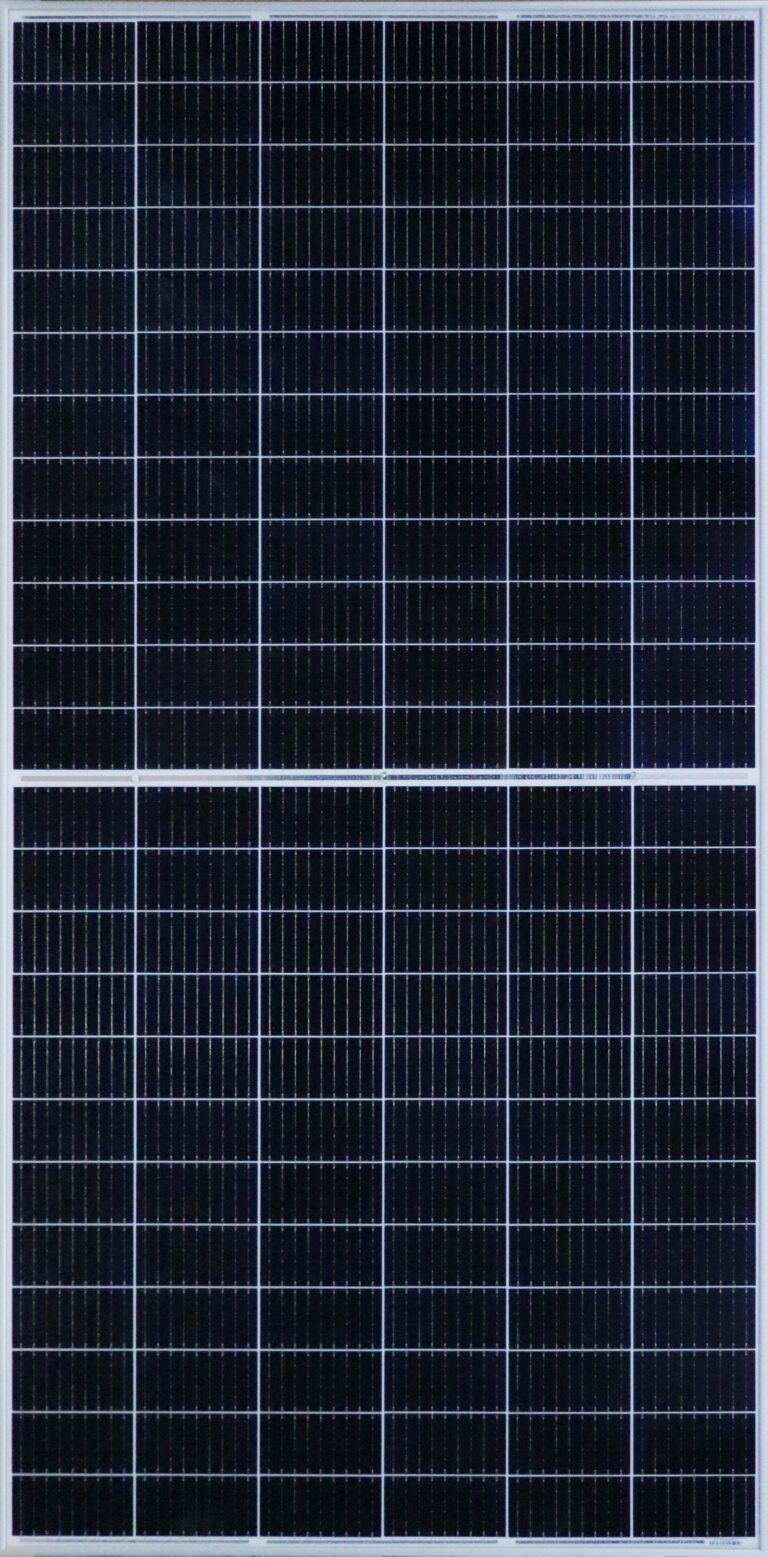
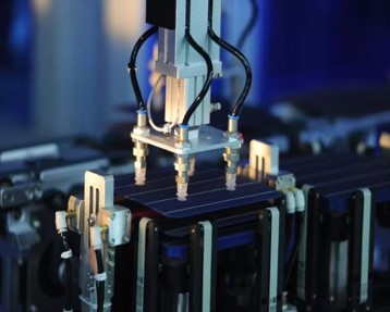
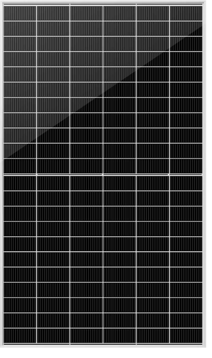
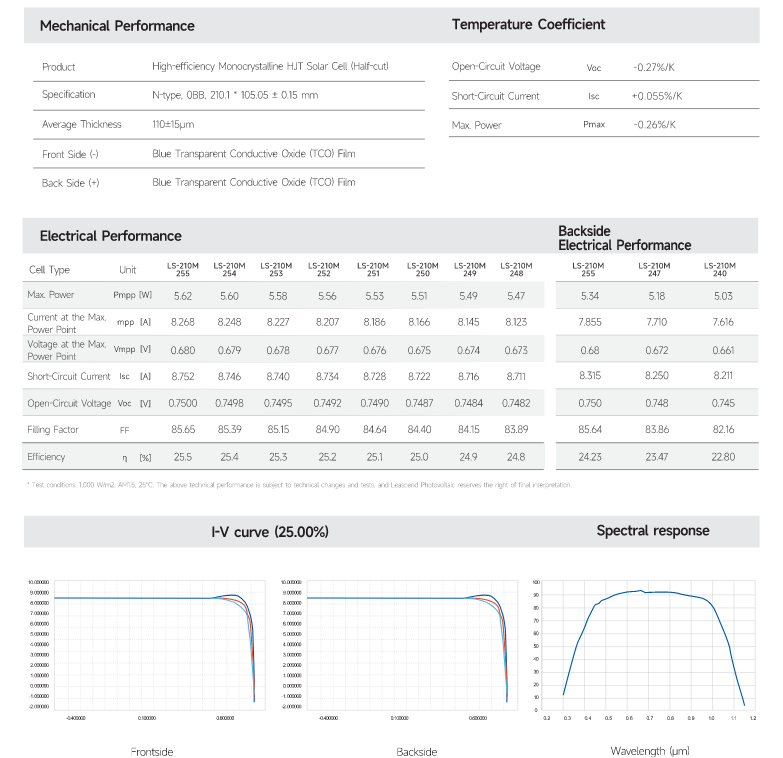
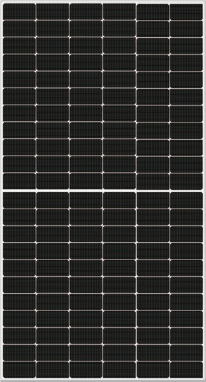
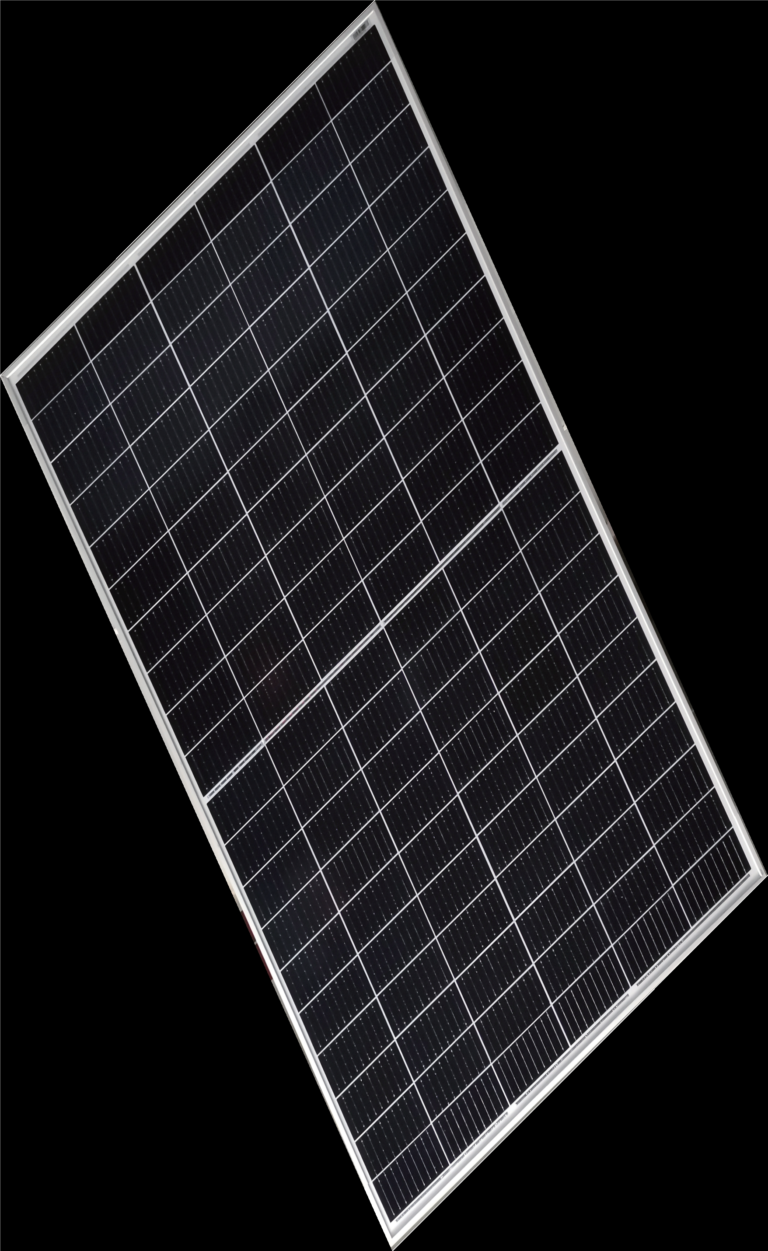
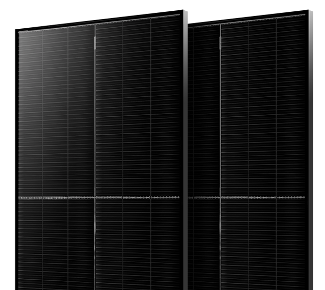
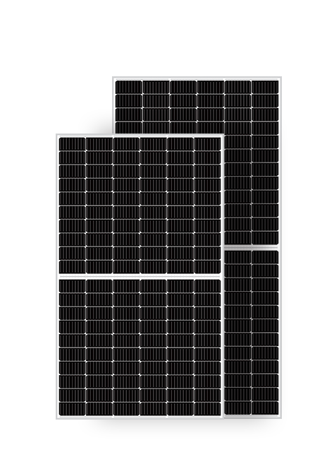
MySolar a solar panel manufacturer, announced in 2023 that it has launched commercially available HJT + perovskite solar cells with a power output of 250 W. The company was founded in 2013 and has since become one of the leading solar panel manufacturers in Poland. HJT + perovskite cells are a new technology with the potential to revolutionize the solar industry.
MySolar a solar panel manufacturer, announced in 2023 that it has launched commercially available HJT + perovskite solar cells with a power output of 250 W. The company was founded in 2013 and has since become one of the leading solar panel manufacturers in Poland. HJT + perovskite cells are a new technology with the potential to revolutionize the solar industry.

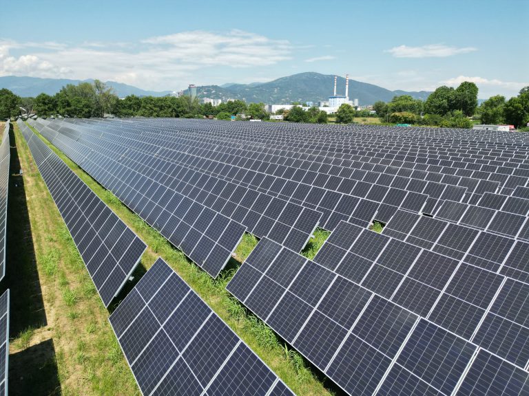
Kapaciteti Srbije za PV Instalacije 1. Obilje pogodnog zemljišta: Srbija ima velike površine zemljišta pogodnog za fotonaponske (PV) instalacije. Topografija zemlje uključuje ravne ravnice, posebno
Serbian Land Capabilities for PV Installations 1. Abundance of Suitable Land:Serbia has vast expanses of land suitable for photovoltaic (PV) installations. The country’s topography includes