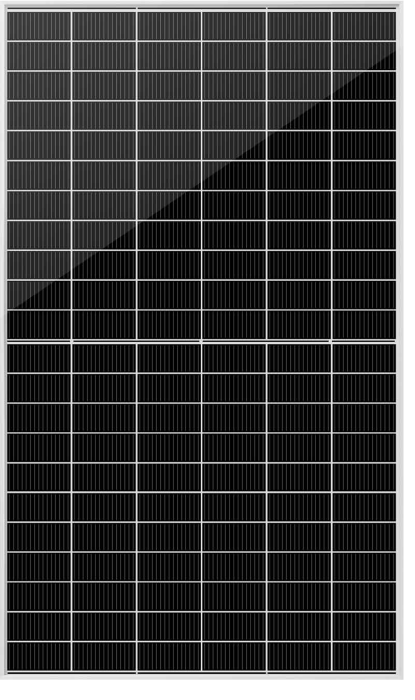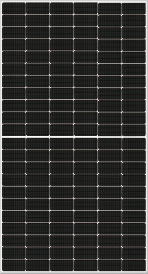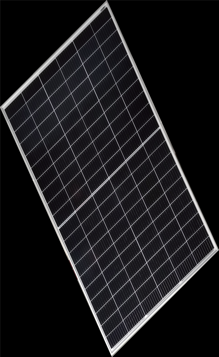

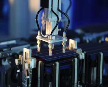
What is 0 BusBar technology?
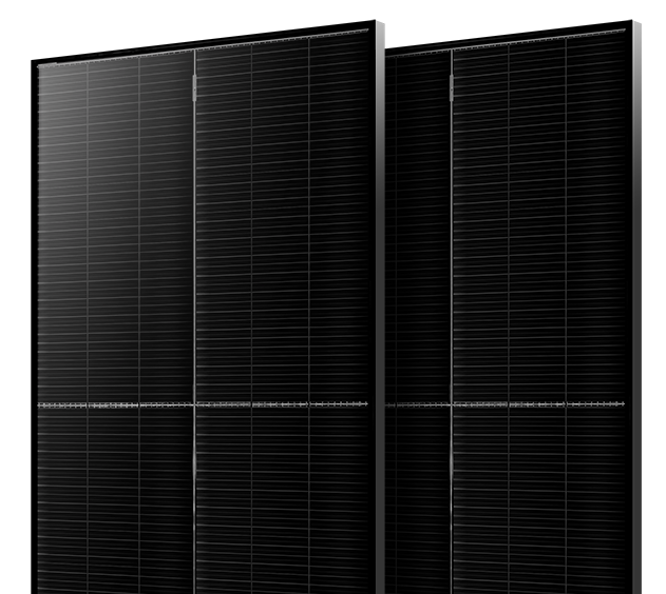
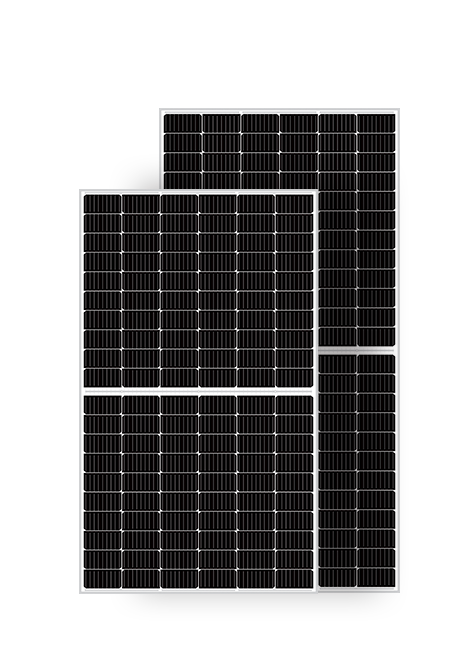
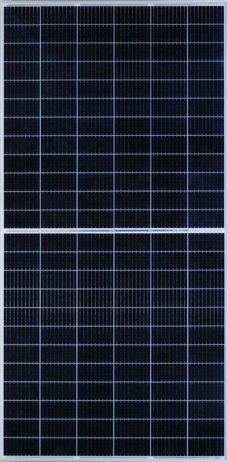
This is a new design for solar cell power conducting design. Instead of stripes as in MBB or SMBB technology, ZBB has very tiny wires for transferring energy into cells and between cells. The simple way explanation for ZBB is the smallest interconnection at the solar cell that is better for the performance and strength of cell.
0BB Cells Interconnection
- First Method SmartWire Connection Technology
The key element of SmartWire is the copper wire composite film, which mainly consists of an electrically
insulating optically transparent film, an adhesive layer on the film surface, and multiple parallel coppers
wires (tabbing ribbons) coated and embedded within the adhesive layer. The copper wires are bonded to
the surface of the film using the adhesive layer, and their surface protruded with a low-melting-point
alloy coating from the adhesive layer.
The alloying of the film and grid is achieved through lamination. The copper wire composite film is
connected to the solar cell, serially connecting the solar cells. It is then overlapped with the encapsulation
film, backsheet, or glass, and a stable electrical connection is formed between the tabbing ribbons and
the grid during the heating lamination process.
The copper wire composite film is laminated on the surfaces of adjacent solar cells to form a series
connection. Compared to conventional solar cell packaging processes, the interconnection of the main
grid solar cells is achieved by using a new type of stringer machine to lay the copper wire composite film
on the front and back surfaces of two cells, enabling the series connection of adjacent cells. After the
cells are interconnected, they are arranged and stacked, and under certain lamination temperatures and
pressure, the copper wires and the solar cell grids are pressed together to form an ohmic contact. - Second Method: Dispension
(1) Dispensing: applying adhesive in the form of multiple adhesive droplets on the surface of each solar
cell; (2) Tabbing: evenly spacing multiple tabbing ribbons perpendicular to the grid lines on the surface of
each solar cell; (3) Fixing: using UV light to cure the adhesive and bond each tabbing ribbon to its
a corresponding solar cell, ensuring direct contact between each tabbing ribbon and the surface grid lines;
(4) Lamination: heating and laminating the solar cell assembly to form alloy connections between the
tabbing ribbons and the grid lines.
The main difference between this process and traditional stringing lies in (1) Dispensing: using adhesive
droplets to bond the tabbing ribbons to the solar cells, enabling both series connection of multiple solar
cells and immobilization of the tabbing ribbons on the cells for subsequent module encapsulation; (2)
Alloying through lamination: achieving ohmic contact through the lamination process.
The advantages of this approach include simple equipment and high stability, while the disadvantages
include potential shadows during EL testing under the tabbing ribbons and insufficient bonding strength
between the tabbing ribbons and the solar cells. - Third Method: soldering dispensation
(1) Soldering: using infrared heating to melt the surface of the solder ribbon, creating a preliminary
connection with the surface and grid lines of the solar cell; (2) Dispensing: applying adhesive droplets at
specified locations on the soldered solar cell-ribbon assembly. The number of adhesive droplets should be carefully controlled to balance process complexity and bonding strength requirements. Typically, 3-8
rows of adhesive droplets are applied based on the shadowing area and mechanical performance needs;
(3) Curing: solidifying the adhesive droplets on the front side of the soldered cell string. The cell string is
then transferred to the next station, flipped under controlled temperature conditions, and adhesive
droplets are applied and cured on the backside of the cell string, forming the final cell string.
Compared to the adhesive bonding approach, the solder adhesive bonding method involves a
preliminary soldering step followed by an adhesive application for reinforcement. The initial connection
between the solder ribbon and the grid lines is established through methods like infrared heating, and
then adhesive is applied and cured to further enhance the stability of the solder ribbon-cell connection.
The advantages of this approach include strong bonding between the solder ribbon and the solar cell,
minimizing the risk of ribbon detachment. However, there is a risk of grid breakage during the soldering
process, and the dispensing process requires high precision, making it a challenging and relatively slow
process

ZBB- 0 BusBars technology - advantages
- The larger surface area of photovoltaic cells, but still in the most popular mounting standard up to 210 mm solar cells size. Thus, more power is obtained from one PV panel.
- Reduced BusBars help the PV module to increase efficiency in the same area.
- Enhanced effectiveness: ZBB technology decreases the electrical resistance within the solar cell, resulting in a more efficient movement of electrons and ultimately increasing the cell's overall energy conversion efficiency. This improved efficiency leads to a greater energy output from the same quantity of sunlight, thereby making ZBB solar cells more productive.
- Certainly, when there are more conducting wires, the distance between them decreases. As a result, the path that the electric current takes becomes shorter, leading to a decrease in energy losses caused by resistance.
- Enhanced ability to tolerate shading: The presence of multiple thin connections in 0BB cells allows for the creation of multiple pathways for electrical current. This reduces the risk of power loss that can occur due to partial shading. This improved shading tolerance is particularly advantageous in installations where solar panel performance can be affected by partial shading caused by objects such as trees or buildings.
- Reduced hotspots: 0BB technology reduces the occurrence of hotspots by distributing the electrical current evenly over the surface of the cell. Hotspots are areas where localized heating happens due to high resistance. These hotspots can cause decreased efficiency and long-term degradation of the cell. 0BusBar technology helps to address and minimize these problems.
- Photovoltaic cells are joined together by a lamination process at temperatures between 140°C and 150°C. The low temperature of the cell-matrix bonding process ideally allows the use of multi-junction cells. This makes the matrix/wire of cells joined using ZBB technology insensitive to losses due to cracks and micro-cracks in individual cells.
Mysolar HJT SOLAR PANEL
Overall, SMBB and ZBB technology represents a significant step forward in solar cell design, helping to improve photovoltaic systems’ performance, efficiency, and reliability, which are vital for the widespread adoption of renewable energy sources and combating climate change.
HJT G12 0BB Solar Cells
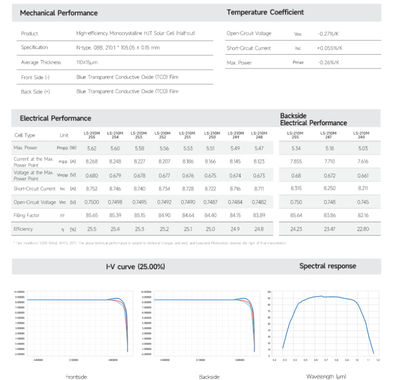
The HJT G12 solar cells are designed with a unique structure that combines monocrystalline silicon and thin amorphous silicon layers. This innovative design is intended to minimize electron recombination losses, thereby enhancing the overall efficiency of the cells and reducing energy loss during the conversion process. The G12 (210mm) cells are further equipped with BusBar technology, which provides several new advantages for heterojunction solar modules. Overall, the utilization of this advanced technology in the development of HJT G12 solar cells has significantly improved the performance and effectiveness of these solar modules.
These are the main features and qualities that can be associated with G12 HJT solar cells.
- Firstly, they are known for their high energy conversion efficiency which can exceed traditional monocrystalline or polycrystalline solar cells. The HJT technology helps to enhance the electron transport properties, thereby contributing to this efficiency.
- Secondly, G12 HJT solar cells have a low-temperature coefficient. This means that their efficiency drops with increasing temperature is lower compared to conventional solar cells. Therefore, they are suitable for regions with high-temperature environments.
- Thirdly, the heterojunction structure of G12 HJT cells allows them to perform well under low-light conditions. This results in higher energy yield, especially during cloudy days or in the early morning and late afternoon.
- Fourthly, HJT solar cells have demonstrated good long-term reliability and durability, ensuring stable performance over the years.
- Finally, G12 HJT solar panels often have a sleek, all-black design, making them aesthetically pleasing for both residential and commercial installations.
HJT Solar Cells 0BB (zero busbar)

The HJT technology is one of the best in high-efficiency solar cells for the new generation. It leads the way in a new revolution in PV technology by integrating the advantages of crystalline silicon and amorphous silicon thin film technology into a single hybrid structure. The HJT solar cell has several advantages, including high efficiency, stability, and simplified manufacturing procedures, all while operating at low temperatures.
The HJT solar cell has an extremely low-temperature coefficient, which helps avoid LID and PID effects. Moreover, there is no color difference between the front and back sides, and the bifaciality is more than 95%. The backside of the solar cell has a significant power generation advantage, which ensures a stable and high-efficiency power output regardless of seasonal circulation and climate change.
Most Popular


Kapaciteti Srbije za Fotonaponsku (PV) Energiju

Serbia Capabilities for Photovoltaic (PV) Energy
Subscribe To Our Weekly Newsletter
Categories
- HJTPV.com
- HJT Technology
- HJT Producers
- HJT Solar Panels
- HJT Solar Panel Mysolar Gold 740W
- HJT Solar Panel Mysolar Gold 640W
- HJT Solar Panel AEsolar COMET 720W
- HJT Solar Panel AESOLAR COMET 650W
- HJT Solar Panel Bi Chaser Akcome 120 Cells
- HJT Solar Panel HuaSun HS-B120DS
- HJT Solar Panel Jinergy JNHM120 Cells
- HJT Solar Panel Risen Hyper-ion
- HJT Solar Panel QW Solar Giwa5 730W
- HJT Solar Panel QW Solar Giwa5 640W
- HJT Solar Panel Risen RSM120
- Cleaning Robot
- HJT Solar CELLS
- News&Knowledge
- Contact
Related Posts

Maximizing Agrivoltaic Performance with HJT/TOPCon Modules
MySolar a solar panel manufacturer, announced in 2023 that it has launched commercially available HJT + perovskite solar cells with a power output of 250 W. The company was founded in 2013 and has since become one of the leading solar panel manufacturers in Poland. HJT + perovskite cells are a new technology with the potential to revolutionize the solar industry.

Innovative 5MW Solar Farm in Northern Italy: Energy Excellence Meets Sustainable Agriculture
MySolar a solar panel manufacturer, announced in 2023 that it has launched commercially available HJT + perovskite solar cells with a power output of 250 W. The company was founded in 2013 and has since become one of the leading solar panel manufacturers in Poland. HJT + perovskite cells are a new technology with the potential to revolutionize the solar industry.

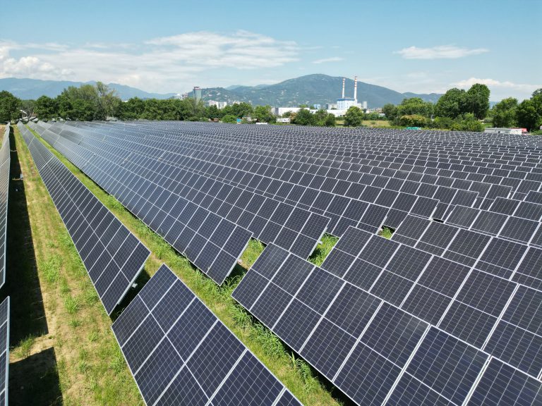
Kapaciteti Srbije za Fotonaponsku (PV) Energiju
Kapaciteti Srbije za PV Instalacije 1. Obilje pogodnog zemljišta: Srbija ima velike površine zemljišta pogodnog za fotonaponske (PV) instalacije. Topografija zemlje uključuje ravne ravnice, posebno

Serbia Capabilities for Photovoltaic (PV) Energy
Serbian Land Capabilities for PV Installations 1. Abundance of Suitable Land:Serbia has vast expanses of land suitable for photovoltaic (PV) installations. The country’s topography includes

